| Amplitude resolution |
3 digits or 1 nV, whichever is greater |
| DC offset |
±5 V, differential or common mode |
| Offset resolution |
3 digits or 0.1 mV, whichever is greater |
| Output limit |
±6 V, sum of DC offset and peak amplitude |
| Sync |
Logic level sync on rear panel
(via BlazeX output) |
|
Data
|
| Data channels |
4 data channels are displayed and graphed (green, blue, yellow, orange) |
| Data sources |
Each data channel can be assigned any of these data sources: X, Y, R, Θ, Aux In 1 to 4, Aux Out 1 to 2, X noise, Y noise, Sine Out Amplitude, Sine Out DC Level, Reference Phase, or Reference Frequency |
| Data history |
All data sources are continually stored at all chart display time scales. The complete stored history of any data source can be displayed at any time. |
| Offset |
X, Y and R may be offset up to ±999 % of the output scale |
| Expand |
X, Y and R may be expanded by ×10 or ×100 |
| Ratio |
X and Y may be ratioed by Aux In 3. R may be ratioed by Aux In 4 |
| Capture buffer |
1 Mpoints internal data storage. Store (X), (X and Y), (R and Θ) or (X, Y, R and Θ) at sample rates up to 1.25 MHz. This is in addition to the data histories for the chart display. |
| Data streaming |
Realtime streaming of data, either (X), (X and Y), (R and Θ), or (X, Y, R and Θ) at sample rate to 1.25 MHz over Ethernet interface |
| Scanning |
One of the following parameters may be scanned: fint, Sine Out Amplitude, Sine Out DC Level, Aux Out 1 or 2. |
|
FFT
|
| Source |
Input ADC, demodulator output, or filter output |
| Record length |
1024 bins |
| Averaging |
Exponential rms |
|
Inputs and Outputs
|
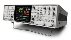
| CH1 output |
Proportional to X or R,
±10 V full scale thru 50 Ω |
| CH2 output |
Proportional to Y or Θ,
±10 V full scale thru 50 Ω |
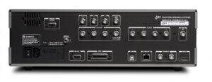
| X and Y rear-panel outputs |
Proportional to X and Y,
±10 V full scale thru 50 Ω |
| BlazeX |
Low latency output of X,
±2.0 V full scale or logic level reference sync output, either thru 50 Ω |
| Aux outputs |
4 BNC D/A outputs,
±10.5 V thru 50 Ω, 1 mV resolution |
| Aux inputs |
4 BNC A/D inputs,
±10.5 V, 1 mV resolution, 1 MΩ input |
| Trigger input |
TTL input triggers storage into the internal capture buffer |
| Monitor output |
Analog output of the signal amplifier |
| HDMI |
Video output to external monitor or TV,
640 × 480, 60 Hz |
| Timebase I/O |
1 Vrms, 10 MHz clock to synchronize internal reference frequency to other units |
|
General
|
| Interfaces |
IEEE488.2, RS-232, USB device and Ethernet. |
| USB flash |
Front-panel slot for USB flash storage of screen shots and data |
| Preamp power |
9-pin D connector to power SRS preamps |
| Power |
60 W, 100/120/220/240 VAC, 50/60 Hz |
| Dimensions |
17″ × 5.25″ × 17″ (WHL) |
| Weight |
22 lbs. |
| Warranty |
One year parts and labor on defects in materials and workmanship |