키사이트 공식대리점
- 공지사항
- 제품
- KEYSIGHT 범용 계측 장비
- 오실로스코프
- 오실로스코프 악세사리
- 디지털 멀티미터 / 볼트미터
- 데이터 수집 제어 장치 (DAQ)
- 소스미터 (SMU)
- DC 전원 공급기 (DC Power Supply)
- DC 전원 분석기 (N6705C)
- DC 모듈러 시스템 전원 공급기 (N6700C)
- DC 전자 로드 (Electronic Load)
- AC 전원 소스 / 분석기
- AC 전력분석기
- LCR Meter 및 저항계
- 주파수 카운터
- 펑션 / 임의 파형 발생기
- 펄스 / 패턴 발생기
- 로직 분석기 (Logic Analyzer)
- GPIB 및 연결 악세사리
- 범용계측기 및 Rackmount Kit
- USB 모듈형 계측기
- Amplifiers
- 휴대용 계측기
- KEYSIGHT RF 장비
- KEYSIGHT IV Curve Tracer
- KEYSIGHT 프리미엄 중고장비
- GW INSTEK
- Chroma
- FLUKE
- HIOKI
- ODA 전원공급기
- ITECH 양방향 파워서플라이
- Sonoma
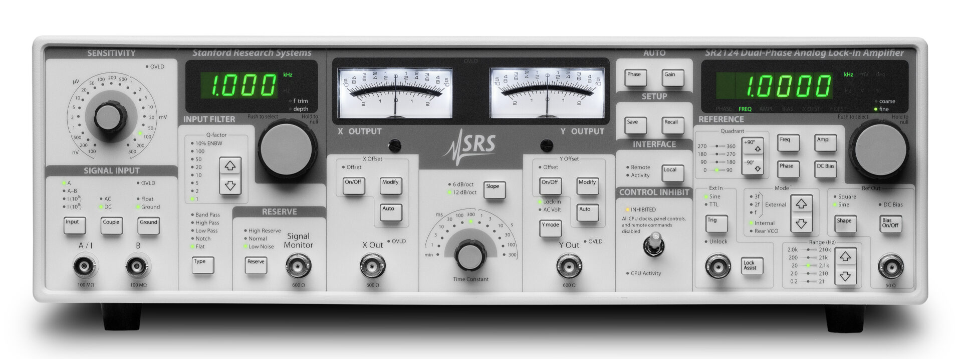
- SRS
- 기타
- 소프트웨어
- KEYSIGHT 범용 계측 장비
- 솔루션
- 프로브 스테이션
- 기술지원/서비스
- 견적요청
- 회사소개