| Signal Channel |
|
| Voltage inputs |
Single-ended or differential |
| Sensitivity (output scale) |
1 nV to 1 V (voltage input) 1 fA to 1 µA (current input) |
| Voltage input range |
10 mV to 1 V (peak) |
| Current input range |
1 µA or 10 nA (peak) |
| Max input |
1 V (peak) or 1 µA (peak) |
| Input impedance |
Voltage input: 10 MΩ + 25 pF, AC or DC coupled Current input: 1 kΩ or 100 Ω to virtual ground |
| Gain accuracy |
±1 % (<200 kHz), ±2 % (to 4 MHz) Signal amplitude must be less than 30 % of input range |
| Noise (rms) |
2.5 nV/√Hz at 1 kHz (10 mV input range, typ.) |
| Harmonic distortion |
–80 dB (<100 kHz), –60 dB (>100 kHz) |
| CMRR |
90 dB to 1 kHz (DC coupled, 10 mV to 100 mV input range) |
| Dynamic reserve |
120 dB (typ) |
| Reference Channel |
|
| Frequency range |
0.001 Hz to 4 MHz |
| Timebase |
10 MHz In/Out (phase locks the internal frequency to other SR865As) |
| Input impedance |
1 MΩ or 50 Ω |
| Phase setting resolution |
360/232 degrees |
| Phase noise |
Int. ref: <0.0001° rms at 1 kHz (100 ms, 12 dB/oct) Ext. ref (typ): <0.001° rms at 1 kHz (100 ms, 12 dB/oct) |
| Phase drift (typ) |
<0.002°/°C below 20 kHz (DC coupled) <0.02°/°C below 200 kHz <0.2°/°C below 4 MHz |
| Harmonic detection |
Detect at N × fref (N<99 and (N × fref)<4 MHz) |
| Dual F reference |
Detect at fdual = |
| Chopper reference |
SR865A drives SR540 Chopper (via Aux Out 4) to lock the chopper to fint |
| Demodulator |
|
| DC stability |
Digital output values have no drift |
| Time constants |
1 µs to 30k s |
| Low pass filters |
Typical RC-type filters or advanced Gaussian/Phase-Linear filters |
| Filter slope |
6, 12, 18 or 24 dB/oct rolloff |
| Synchronous filter |
Available below 4 kHz |
| Harmonic rejection |
–80 dB |
| Low latency output |
Rear-panel BlazeX output with <2 µs delay (plus LPF rise/fall times). |
| Internal Oscillator |
|
| Frequency range |
0.001 Hz to 4 MHz |
| Frequency accuracy |
25 ppm + 30 µHz (with internal timebase) |
| External timebase |
10 MHz timebase input/output (on rear panel) |
| Frequency resolution |
6 digits or 0.1 mHz, whichever is greater |
| Sine Output |
|
| Outputs |
Single-ended or differential |
| Output impedance |
50 Ω source |
| Amplitude |
1 nVrms to 2 Vrms (amplitude is differential into 50 Ω loads). Output is halved when using in single-ended mode. Output is doubled when driving a high impedance load. |
| Amplitude resolution |
3 digits or 1 nV, whichever is greater |
| DC offset |
±5 V, differential or common mode |
| Offset resolution |
3 digits or 0.1 mV, whichever is greater |
| Output limit |
±6 V, sum of DC offset and peak amplitude |
| Sync |
Logic level sync on rear panel (via BlazeX output) |
| Data |
|
| Data channels |
Four data channels are displayed and graphed (green, blue, yellow, orange) |
| Data sources |
Each data channel can be assigned any of these data sources: X, Y, R, θ, Aux In 1 to 4, Aux Out 1 to 2, X noise, Y noise, Sine Out Amplitude, Sine Out DC Level, Reference Phase, or Reference Frequency. |
| Data history |
All data sources are continually stored at all chart display time scales. The complete stored history of any data source can be displayed sat any time. |
| Offset |
X, Y and R may be offset up to ±999 % of the output scale |
| Expand |
X, Y and R may be expanded by × 10 or × 100 |
| Ratio |
X and Y may be ratioed by Aux In 3. R may be ratioed by Aux In 4. |
| Capture buffer |
1 Mpoint internal data storage. Store (X), (X and Y), (R and θ), or (X, Y, R and θ) at sample rates up to 1.25 MHz. This is in addition to the data histories for the chart display. |
| Data streaming |
Realtime streaming of data, either (X), (X and Y), (R and θ), or (X, Y, R and θ) at sample rates up to 1.25 MHz over the Ethernet interface. |
| Scanning |
One of the following parameters may be scanned: fint, Sine Out Amplitude, Sine Out DC Level, Aux Out 1 or 2 |
| FFT |
|
| Source |
Input ADC, demodulator output, or filter output |
| Record length |
1024 bins |
| Averaging |
Exponential rms |
| Inputs and Outputs |
|
| CH1 output |
Proportional to X or R (±10 V full scale thru 50 Ω) |
| CH2 output |
Proportional to Y and θ (±10 V full scale thru 50 Ω) |
| X and Y outputs |
Proportional to X and Y (rear panel) (±10 V full scale thru 50 Ω) |
| BlazeX |
Low latency ouput of X, ±2.0 V full scale or logic level reference sync output, either thru 50 Ω |
| Aux outputs |
4 BNC D/A outputs, ±10.5 V thru 50 Ω, 1 mV resolution |
| Aux inputs |
4 BNC A/D inputs, ±10.5 V, 1 mV resolution, 1MΩ input |
| Trigger input |
TTL input triggers storage into the internal capture buffer |
| Signal monitor |
Analog output of the signal amplifier |
| HDMI |
Video output to external monitor or TV (640 × 480, 60 Hz) |
| Timebase I/O |
1 Vrms, 10 MHz clock to synchronize internal reference to other units |
| General |
|
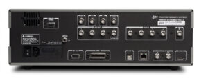
| Interfaces |
GPIB (IEEE-488.2), RS-232, USB and Ethernet |
| USB flash |
Front-panel slot for USB flash storage of screen shots and data |
| Preamp power |
9-pin D connector to power SRS preamps |
| Power |
60 W, 100/120/220/240 VAC, 50/60 Hz |
| Dimensions |
17” × 5.25” × 17” (WHD) |
| Weight |
22 lbs. |
| Warranty |
One year parts and labor on defects in materials and workmanship |
| Ordering Information |
|
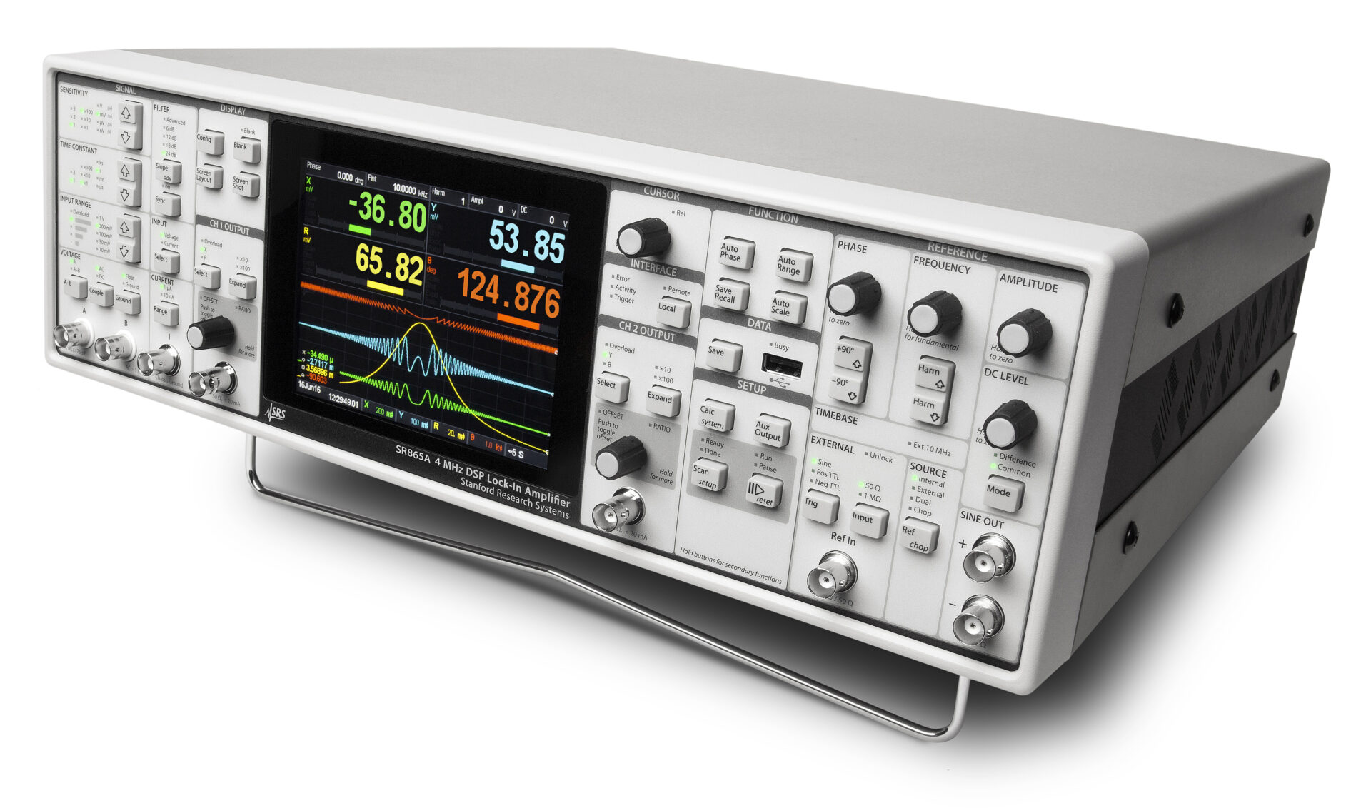
| SR865A |
4 MHz lock-in amplifier $7950 |
| SR550 |
Voltage preamplifier (100 MΩ, 3.6 nV/√Hz) $750 |
| SR552 |
Voltage preamplifier (100 kΩ, 1.4 nV/√Hz) |
| SR554 |
Transformer preamplifier (0.091 nV/√Hz) |
| SR555 |
Current preamplifier |
| SR556 |
Current preamplifier |
| SR540 |
Optical chopper |